

Release Date: Aug 12,2022
capacitive crosstalk
Two signal lines, called noise source and noise sink. Because of the capacitive nature of the two lines, noise on the source can couple to the receive line, causing current to be injected into the receive line. On a transmission line, current travels in both directions Z until it is dissipated at the source and the load. The resulting voltage spike on the line is determined by Z. When the current pulse reaches Zs and ZL, it is dissipated along the resistance and the voltage is proportional to the impedance. Reflections occur if the impedances at the source or load do not match. For unterminated loads, the voltage spikes on ZL can be large. Terminating the load can effectively reduce the input voltage noise of the next device. But there will be losses.
Capacitive crosstalk can also be reduced by separating the lines. If there is enough space left on the circuit board, the signal lines should be kept as large as possible. Because the farther the signal lines are separated, the less capacitance and the less the crosstalk will be. In addition, placing a ground wire between adjacent signal lines can also effectively reduce capacitance. As shown in Figure 2, the signal is now coupled to ground and no longer to adjacent lines.
It should be noted that the ground wire must be a complete ground, if it is only connected to the ground plane at the end of the line, it will have a fairly high impedance. To have a good ground, a quarter wavelength of the highest frequency component of the signal at each interval should be punched on the ground wire and connected to the ground plane.
Inductive crosstalk
Inductive crosstalk can be thought of as unwanted signal coupling between the primary and secondary windings of the transformer (current loops on the board). The amount of undesired signal coupled to the load depends on the size and separation of the loop, and also on the affected load impedance. The converted energy increases as the loop gets larger and closer together. At the load, the secondary loop, the magnitude of the signal increases with the load impedance.
The loop inductance (L) increases with the size of the loop. When two loops are interconnected, one will be the main inductance (LP) and the other will be the secondary inductance (LS), as shown in Figure 3. Although the signal line will not be The transformer is purposefully designed to be loosely coupled, however, it can cause interference on the secondary ring.
If the inductive crosstalk is a loop loop caused by manual wiring, it is relatively easy to solve, as long as the loop is removed, but it is a challenge to deal with this kind of loop. If crosstalk is caused by a source and return signal loop, it is obviously not possible to cut the loop, but keeping the load impedance low will often minimize the effects of crosstalk. Figure 4 illustrates a simplified description of a natural secondary loop with a load. Zs here is the inherent impedance of the secondary loop. Note the series current (Is), because the impedances are also in series, Is is the same everywhere in the loop. For a constant Is, the voltage drop across the largest impedance is the largest. On unterminated lines, this is often the load on the end of the line; that is, on the input of the receiving device.

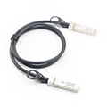
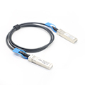
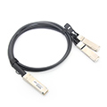
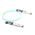
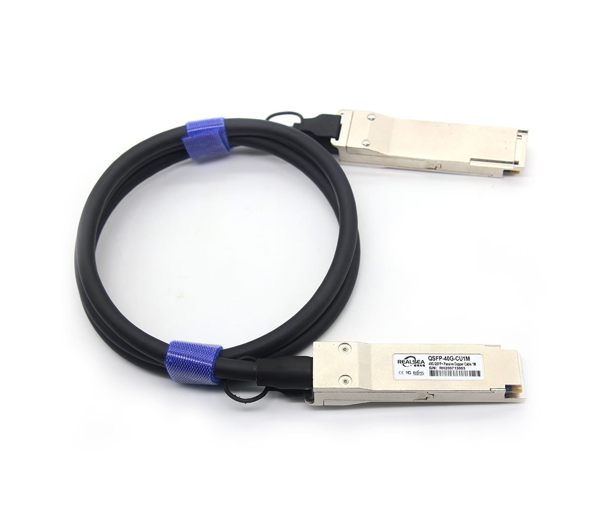
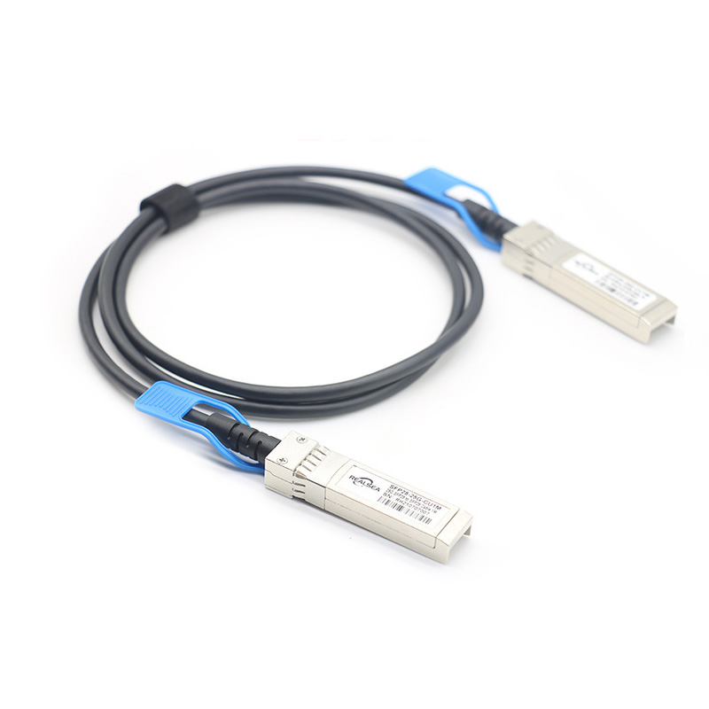
25G SFP28 DAC is a 25GBASE-CR direct attach copper cable for data center environment. It provides a high speed, cost-effective alternatives to fiber optics in 25GbE Ethernet applications.

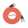
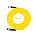
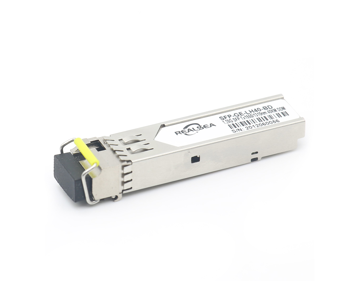
fiber pigtail is typically a fiber optic cable with one end factory pre-terminated fiber connector and the other exposed fiber.
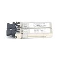
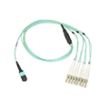
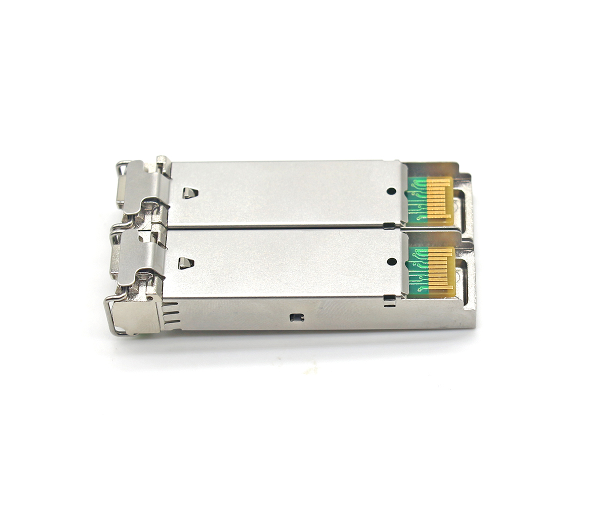
This Article just briefly overviews 10G and 25G Ethernet (25Gb) technologies, focusing on the SFP+ transceiver and SFP28 transceiver.
Get in contact with our customer service
Contact Now
Send email for the latest news and excluive offers
Products

About
Cases
News