

Release Date: Aug 12,2022

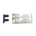
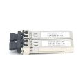
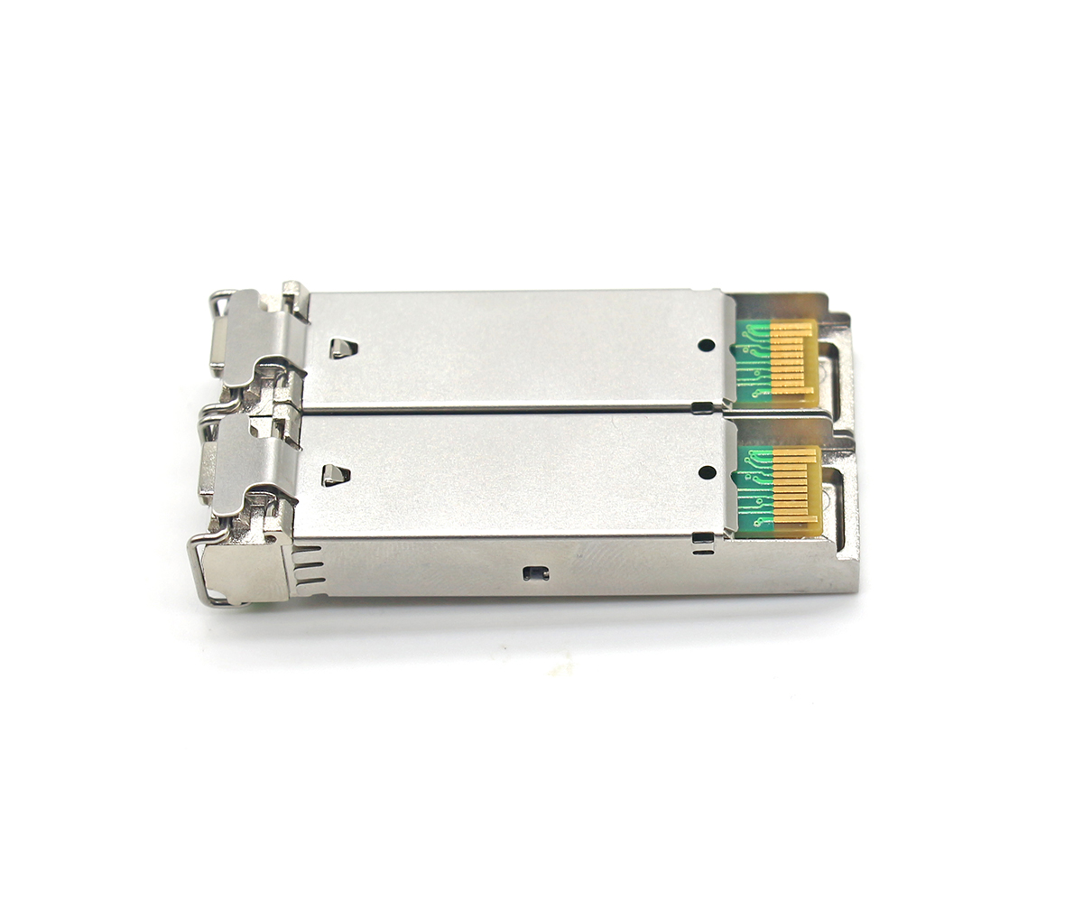
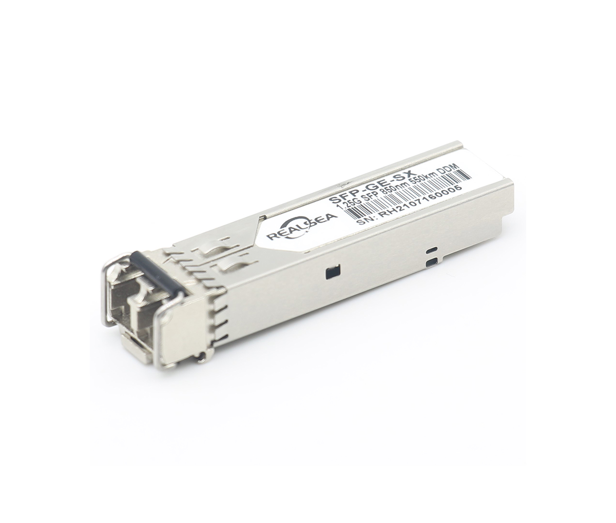
In miniaturized optical transceiver modules such as SFP and SFF circuits, due to the increase in wiring density, the effect of crosstalk between interconnecting lines has become very obvious, especially under the action of high-frequency electrical signals above 2.5G, this distribution The coupling effect of nature cannot be ignored. This paper briefly expounds the analysis and calculation of crosstalk.
The fundamental reason for the formation of crosstalk is that the signal changes cause the surrounding electromagnetic field to change, especially for high-speed signals, the time of the rising and falling edges of the signal can reach the ps level, the high-frequency components are very rich, and the parasitic capacitance and inductance between the signal lines are easy. Become a coupling channel for crosstalk signals. In the optical transceiver module, especially the LC miniaturized package module, the coupling between the two adjacent signal lines at the transmitting and receiving ends and between the ground planes will form crosstalk, so the crosstalk is also called a three-wire system. There are inductive components and capacitive components distributed on the transmission line, so the crosstalk between the entire signals consists of two parts, namely capacitive coupling interference and inductive coupling interference. It can be seen from Cwire=Csub+Cint and Cint=(εdi/tdi) ×W×L that the capacitance on the interconnection line is composed of the capacitance between the interconnection line and the substrate and the capacitance between the interconnection lines. Capacitance is inversely proportional to the spacing between them. With the development of the technology, the wiring density on the circuit board is getting larger and larger, the spacing between the interconnecting lines is getting smaller and smaller, and the coupling capacitance Cint between the interconnecting lines is more and more than the capacitance Csub between the lines and the substrate. The larger the chip, the greater the electromagnetic coupling effect between the interconnect lines, as the chip operating frequency continues to increase, resulting in an increasing mutual influence between the interconnect lines.

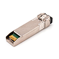
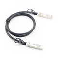
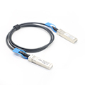
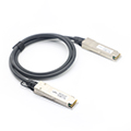
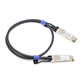
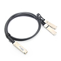
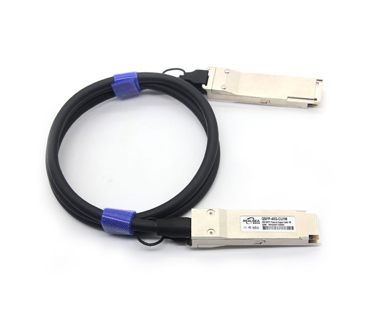
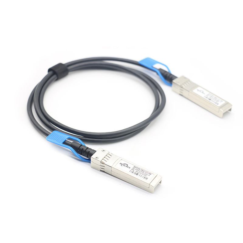
25G SFP28 DAC is a 25GBASE-CR direct attach copper cable for data center environment. It provides a high speed, cost-effective alternatives to fiber optics in 25GbE Ethernet applications.

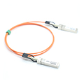
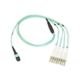
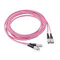
fiber pigtail is typically a fiber optic cable with one end factory pre-terminated fiber connector and the other exposed fiber.
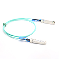
This Article just briefly overviews 10G and 25G Ethernet (25Gb) technologies, focusing on the SFP+ transceiver and SFP28 transceiver.
Get in contact with our customer service
Contact Now
Send email for the latest news and excluive offers
Products

About
Cases
News